
Table of Contents
Introduction
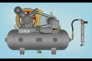
By connecting an air compressor to any end-user tool using a pipe as a medium, you can create an air compressor piping diagram. As simple as it might appear, creating your pipping diagram is a rather complicated procedure. To come up with proper piping, you would also need the specific requirement for your project. Furthermore, such specifications comprise adequate ventilation and separation, as is the case for a spraying work area. Such a diagram demands that it must be produced in close connection with an outside wall with intense air filtering. It basically means you would have to position the station near an exterior wall. Also, a curling machine allows you to calm the machine first, which can be put close to the outside wall as well.
Basic Guidelines for Air Compressor Piping Diagrams
- The first airdrop should be 50 Feet from the compressor for maximum efficiency. An individual air-user can also use each airdrop. Most air – users should not be connected to the same drop.
- Closed valves should be mounted to allow air to stop along the way to preserve the filter as required.
- Drain valves help the system to remove pollutants that accumulate, particularly during times of heightened usage. Drain the machine regularly and increase the cycles as appropriate.
- Try adding receiver at the end of the line to meet the peak air specifications.
- Learn and grasp the pipe specifications before implementation. If required, use professional support.
- The discharge pipe must be of the same height as the outlet of the compressor.
- The inlet and discharge outlet must be constructed in such a way as to allow the air to flow seamlessly through the entire pipe diagram.
- The major routes must be at least 10 cm away from the air compressor to enable the air to cool at room temperature until it passes through the pipes.
- The Components Used: A pipe system’s material can serve as an important indicator if you’re trying to get a quality pressurized air. You can get pipes in several different components, including steel compressed air pipes, which appear to be thicker and can handle elevated pressures and temperatures. They are, though more costly, bulkier, and they often corrode quickly. Plastic air pipes, on the other hand, are thinner and have no corrosion problems. Lubricant degradation will lead to leakage in the air system, and this is not something you want to take a chance on. They are, however, unable to tolerate high temperatures. Aluminium pipes are also available, and they are the most favoured because they can be quickly cut and assembled. It is necessary to remember that the use of incorrect material in the air compressor pipe diagram can lead to severe injury or even death, destruction, or mechanical failure.
- Distance and Size: The sizes of the pipes and the distance to the end-user unit have a direct impact on the airflow at the point of use. When the pipes are too short, the air pressure can rise above the recommended end-user levels. Similarly, if the gap between the pipe structure and the point of use is too far, the pressure can fall below the prescribed limit. It might lead to an overworked device that can lead to premature wear and expensive repairs. Besides, an increase in pressure will lead to an increase in energy needs, which will further increase costs.
- Put the layout into consideration: If it comes to pipe layout, you can either get a straight pipe layout or a loop layout. Square plants are going well with a pipe-like loop. Air passes through the loops and drops down at each point of application. The straight pipe layout, on the other hand, is used in longer and narrower plants and appears to be less costly than the loop one. When deciding which layout is acceptable for the construction of your plant, it is often crucial to consult an expert to prevent excessive pressure drops or accruing unnecessary expenditure.
- Try to avoid Sharp Angles: When you have a lot of sharp angles in the pipe diagram, the airflow speed runs down, and as a result, it reduces the strain. Abrupt twists often disrupt the passage of air. As such, the most effective direction is a straight one, and it is also not advised to have several sharp angles in the pipe diagram.
- Ensure Moisture Levels are regulated: Moisture has detrimental effects on pipes as it appears to kill the pipes by the resultant corrosion. Besides, it can contaminate other areas of the system, clog the nozzle and create system blockages. Worse still, we cannot stop rain in the compressor world because air will still have a certain level of moisture. Although when dealing with air compressors, we will try to regulate the volume of moisture. You can also reduce the moisture when it is near your workspace by moving the supply inlet from the bottom to the top of the compressor. You could also use an aftercooler that is known to drain more than 50 per cent of the liquid from the air compressor pipe diagram.
- Control Obstructions: Corrosion is the leading cause of clogging. Obstructions typically clog the pipe structure, and this will severely reduce the air pressure. It is easy to detect an obstruction within your pipe since you can find very high pressure right before the congestion happens and external pressure after the obstruction. These blockages will be kept in check by using good air filters to eliminate specific particles that clog the pipe system. You may either use a short pipe or reduce the gap the air needs to pass in.
- Temperature: Temperature variations in the working area are likely to influence the consistency of the compressed material, mainly where the pipes are not housed in the same space. The pipes can move underground or into other rooms which may be exposed above or below the prescribed temperature limit. Excessive heat can cause the pipes to overheat, make them wear, and that can be unsafe for consumers as well.
- Maintenance Requirement: When preparing the compressed air pipe diagram, you will need to prepare for potential maintenance needs. This includes the construction of a bypass pipe to continue carrying compressed air while servicing is necessary. The bypass pipe should be fitted with a valve to shut off the air supply while the main pipe is restarted. It would be best if you also planned extra pipes to satisfy rising demand, enabling more air to be routed to as many end-user machines as necessary.
Conclusion
You will most likely keep your air compressor, piping and your health safe by strictly following the tips outlined in this article. More so, you will also be able to use your air compressor and put it to the best use.